Data center architecture has evolved, with the traditional 3-Tier design being replaced by the more efficient Spine-and-Leaf architecture. This modern approach features a 2-layer design, enhancing data flow and reducing latency. Each leaf switch connects to every spine switch, eliminating bottlenecks and ensuring predictable performance. Scaling is simplified by adding more spines or leaves, and built-in redundancy minimizes the impact of any component failure.
Understanding the following key principles and calculations, such as determining the maximum number of leaf switches and servers, helps maximize network efficiency, and helps bring you the basics of Spine-and-Leaf Architecture as you start to navigate your data centers transition from old ways to a more modernized structure.

Modernization of Data Center Architecture with a Spine-and-Leaf Network
Modern Data Center Architecture: Embracing Spine-and-Leaf Design
Modern Data Center Architecture: Embracing Spine-and-Leaf Design
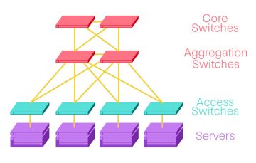
In recent decades, the landscape of data center architecture has undergone significant transformation. The traditional 3-Tier or 3-Layer design—comprising Access, Aggregation, and Core layers—featured a South-to-North data flow. This model, however, has proven to be less than ideal in addressing modern data demands.
Limitations of the 3-Tier Design
In the 3-Tier model, data had to traverse a hierarchical path: from the server to the aggregation switch, up to the core switch, and then back down. This method introduced latency and created traffic bottlenecks.
Advantages of Spine-and-Leaf Architecture
Advantages of Spine-and-Leaf Architecture
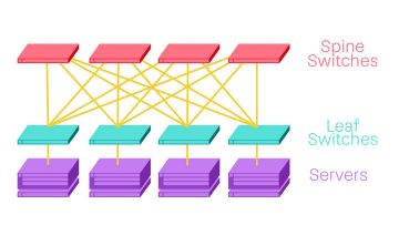
The Spine-and-Leaf architecture was specifically developed to overcome the limitations of the outdated 3-Tier system, which has been replaced by the more efficient Leaf-Spine architecture, characterized by an East-to-West data flow within a streamlined 2-layer design.
Here’s how it works:
Leaf Switches - connected to servers, storage, WAN, or internet devices.
Spine Switches - acting as the backbone, interconnecting all the Leaf switches.
In this setup, every Leaf switch is connected to every Spine switch in a fully meshed topology. This uniform connection ensures that data crosses the same number of devices each time, resulting in more predictable latency.
The Spine-and-Leaf architecture represents a pivotal advancement in data center design, offering enhanced efficiency, scalability, and reliability to meet modern demands.
Key Principles of Spine-and-Leaf Architecture
Key Principles of Spine-and-Leaf Architecture
When considering Spine-and-Leaf Architecture, it's important to remember the following key principles to ensure efficient, scalable, and reliable network performance:
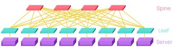
Leaf-to-Spine Connections
Every Leaf is connected to every Spine, but not to otherLeaf switches, and Spines are not connected to otherSpine switches.
Port Density and Leaf Switches
The port density at the Spine defines the maximum numberof Leaf switches.
Example:
4 line cards, 36 x 100G ports/card – 4 x 36 x 100G
Uplink Ports and Spine Switches
The number of uplink ports at the Leaf switch defines themaximum number of Spine switches.
Example:
4 uplink ports (to the Spine) = 4 x 100G
Downlink Ports and End-Devices
The downlink port count at the Leaf switch andoversubscription ratio define the maximum number ofconnected end devices.
Example:
48 downlink ports (to the Servers) = 48 x 25G
For a more in-depth exploration of the Spine-and-Leaf Architecture, have a look at our Structured Cabling Design Guide for Large IT/Service Provider Data Centers.
Calculating Network Capacity in Spine-and-Leaf Architecture
Calculating Network Capacity in Spine-and-Leaf Architecture
To calculate network capacity, here are some helpful formulas for determining key aspects of your Spine-and-Leaf Architecture.
To calculate the maximum number of leaf switches:
1. Determine the total ports per Spine Switch: Include all the ports in your line cards.
2. Multiply by the number of Spine Switches: This gives the total available spine ports.
3. Divide by the number of uplink ports in a Leaf Switch: This gives the maximum number of leaf switches.
To calculate the number of servers or hosts:
Multiply the number of downlink ports in a Leaf Switch by the number of Leaf Switches: This gives the total number of connected end-devices.
By using these formulas, you can easily determine the network capacity and ensure efficient planning for your Spine-and-Leaf Architecture.
Products for Leaf-Spine Networks


Let’s connect. Our experts are here to support every step of your way.
Whether you need help with your current implementation or planning for the future, we can help. Complete this form to get started.
Thank you!
A Corning representative will be contacting you shortly about your inquiry. Should you need immediate assistance please call our customer service line at +49 30 5303 2100.