Multimode fiber remains a leading optical media in the data center for short-reach distances up to 150 meters. Forty and 100G multimode fiber backbones are being deployed to facilitate data center 10G and 25G server connections. Multimode fiber enables the utilization of vertical-cavity surface-emitting lasers (VCSELs) to provide synergistic, low-cost optical connectivity and electronic solutions. OM3 and OM4 laser-optimized 50/125 μm multimode fibers are the fibers of choice, but recently TIA approved a 50/125 μm wideband multimode fiber (WB MMF) for industry consideration. ISO/IEC JTC 1/SC 25 has approved the OM5 designation for inclusion into the ISO/IEC 11801-1 document, and TIA has harmonized with the ISO/IEC 11801-1 document and implemented the OM5 nomenclature. The industry is moving quickly, as 40 and 100G Ethernet standards and proprietary multimode fiber transmission variants become commercially available that readily support transmission on standard multimode fiber to 300 meters and beyond.

40|100G Multimode Fiber Connectivity in the Data Center
40|100G Multimode Fiber Connectivity
 |
||
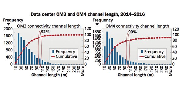
| Figures 1 and 2: Data Center OM3 and OM4 Channel Length Distribution |
Data Center Multimode Fiber Connectivity Distances
Ethernet transmission standards develop guidance based on specific criteria, including technical and commercial feasibility. A primary objective is to deliver economical solutions that meet distance objectives representative of deployed multimode fiber connectivity channel lengths. Corning has tracked and modeled multimode and single- mode fiber connectivity data center channel lengths for an extended time period. Trends have shown that as data rates have increased from 10G to 40G to 100G, the 100 meter channel distance represents approximately 95 to 90 percent of the deployed OM3/OM4 channel lengths, as shown in Figures 1 and 2. In other words, for the vast majority of data center links, a 100 meter channel distance is more than sufficient to meet their needs.
Another contribution to the higher multimode fiber percentage at 100 meters has been the cannibalization of copper connectivity. For data centers operating at 10G and higher data rates, copper connectivity has been relegated to server connections where twinaxial copper cable is mostly used. Twinaxial copper cable is expected to continue as the primary server interconnect until 50G, where optical interconnects will be preferred, due to distance limitations with copper connectivity. Servers with 50G I/O are anticipated in 2018.
40G and 100G Transmission and Connectivity Methods
Parallel Optics
When the Ethernet Standards 802.3ba task group first addressed 40G multimode fiber transmission, the 850 nm VCSEL modulation capability was unable to deliver a single 40G wavelength variant. IEEE chose parallel optic transmission based on development simplicity and the ability to provide a reliable, low-cost solution. Parallel optics differs from traditional duplex fiber optic serial communication in that data is simultaneously transmitted and received over multiple optical fibers. 40GBASE-SR4 parallel optics requires eight OM3 or OM4 fibers with 10G transmission on each fiber: four fibers (four fibers x 10G/fiber) to transmit (Tx) and four fibers (four fibers x 10G/fiber) to receive (Rx). The 802.3ba standard specifies a maximum 100/150 meter distance (OM3/OM4). Proprietary extended-reach 40GeSR4 parallel optic transceivers are now available to support distances up to 300/400 meters (OM3/OM4). With MTP®-connectorized EDGETM solution components, the extended-reach 40GeSR4 transceiver delivers up to 330/550 meters (OM3/OM4).
Ethernet 802.3ba 100GBASE-SR10 also used 10G per fiber and required 20 OM3 or OM4 fibers (10 fibers x 10G/fiber Tx and 10 fibers x 10G/fiber Rx), but had limited industry demand. As VCSEL technology evolved, 25G modulation rates became available, so there is now the Ethernet 802.3bm 100GBASE-SR4 transmission variant that has identical connectivity requirements as the 40GBASE-SR4. See Figure 3. The 802.3bm standard specifies up to 70/100 meters (OM3/OM4). Proprietary extended-reach 100GeSR4 transceivers are also now available to service up to 200/300 meters (OM3/OM4).
Parallel optics enables breakout capabilities in which the transceiver’s MTP interface can be broken out into multiple duplex LC connections. For example, 40GBASE- SR4 to 4 x 10GBASE-SR duplex connections.
Wavelength Division Multiplexing (WDM)
Ethernet multimode fiber transmission relied on duplex fiber transmission up to 10GBASE-SR. Beyond 10G, the VCSELs were unable to support a serial 40G duplex fiber solution. The Ethernet 802.3ba task group evaluated WDM and parallel technologies for 40/100G and selected parallel optics for the standard, as it would result in faster and more economical near-term 40/100G deployments.
10GBASE-SR is a widely deployed standards-based technology that uses OM3/OM4. The 10GBASE-SR variant also includes OM1 and OM2 options but with minimal traction. 10G connectivity using Corning’s EDGE8TM (base-8) MTP® trunk cables with an MTP-to-LC universal polarity module and/or MTP-to-LC universal polarity harness easily provides four breakout duplex LC circuits per 8-fiber MTP connector. The duplex LC connector plugs into the 10GBASE-SR SFP transceivers. 10GBASE-SR deployments that utilize MTP trunk cables easily migrate to 40GBASE-SR4 parallel optics.
The migration of brownfield 10GBASE-SR to 40G in cabling environments without MTP connectivity in the optical backbone led transceiver manufacturers to offer proprietary 40G transceivers with a duplex multimode fiber interface. Two proprietary variants can be considered, 40G BiDi and 40G SWDM, which are now both commercially available.
The 40G BiDi transceiver has two 20G optical channels that are bidirectionally transmitted and received over each fiber. This feature results in an aggregate bandwidth of 40 Gbps with a duplex LC cable. The 40G BiDi transceiver is specified up to 100/150/200 meters on OM3/OM4/OM5. With Corning EDGE and EDGE8 solutions, the 40G BiDi transceiver delivers up to 100/200/200 meters on OM3/OM4/OM5 connectivity. 100G BiDi transceivers were recently commercially released and use the same optical connectivity as the 40G BiDi. 100G BiDi has two 50G optical channels that are bidirectionally transmitted over each fiber and is specified up to 70/100/150 meter distances on OM3/OM4/OM5.
| Figure 3: 40GBASE-SR4 and 100GBASE-SR4 Parallel Transmission |
 |
||
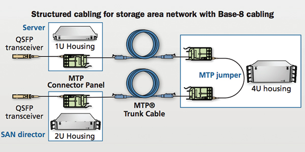
| Figure 4: EDGE8 MTP Trunk Cable with MTP Module Connectivity for 40GBASE-SR4 and 100GBASE-SR4 |
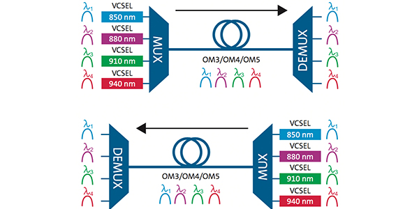
The 40G SWDM transceiver multiplexes four 10G wavelengths that are codirectionally transmitted over each simplex fiber to provide 40G total bandwidth. See Figure 5. The 40G SWDM transceiver is specified to support up to 240/350/440 meters on OM3/OM4/OM5. The SWDM transceiver has been designed to primarily operate over OM3/OM4 fiber in existing brownfield data centers. 100G SWDM transceivers were recently commercially released and are specified to 70/100/150 meter distances on OM3/OM4/OM5. The 100G SWDM4 transceivers achieve an aggregate 100G data rate utilizing four 25G wavelengths. Neither SWDM nor BiDi are capable of port breakout functionalities, which are supported by parallel optics.
 |
||
| Figure 5: 40G SWDM Transmission |
Summary
Multimode fiber connectivity continues to provide reliable and low-cost solutions in the data center. Based on the anticipated economics of fiber connectivity and transceivers, it is expected that for 40 and 100G deployments, the multimode fiber/transceiver use cases will be as shown in Table 1 below. As the historical deployment data shows, 90 percent of OM3/OM4 channels in the data center are less than 100 meters. However, for the few customers who have channel lengths out to 300 meters, there will be several fiber and transceiver combinations to provide the necessary reach, ensuring that multimode connectivity deployed in the data center today will remain valuable well into the future.
| Reach | 40G Multimode Fiber Type/Transceiver | 100G ultimode Fiber Type/Transceiver |
| ≤ 100m | OM4/SR4 OM4/BiDi OM4/SWDM |
OM4/SR4 OM4/BiDi OM4/SWDM |
| >100-500 m | OM4/eSR4 OM4/SR4 OM4/BiDi* OM4/SWDM |
OM4/eSR4 OM4/SWDM |
Table 1: Expected Multimode and Transceivers Deployment Scenarios
Note: OM3 not shown in table for simplicity. Contact Corning for specific OM3 guidance.
*BiDi up to 200 m using Corning EDGE and EDGE8 solutions.
Doug Coleman
Corning Optical Communications
Last update: December 2024
Let’s connect. Our experts are here to support every step of your way.
Whether you need help with your current implementation or planning for the future, we can help. Complete this form to get started.
Thank you for your submission!
A Corning representative will be contacting you shortly about your inquiry. Should you need immediate assistance please call our customer service line at +49 30 5303 2100.