Considerations in outside fiber-optic cable design | Optical Communications | Corning

Considerations in outside fiber-optic cable design

Considerations in outside fiber-optic cable design

Loose tube, ribbon, and micro loose tube cables are all options for outside-plant fiber cabling

by Derek Whitehurst

Since the development of fiber optic cable in the mid-1970s, there has been a steady stream of innovations in manufacturing, materials, and network systems which have advanced the design and capabilities of outside cables including loose tube, ribbon, and micro loose tube cables.

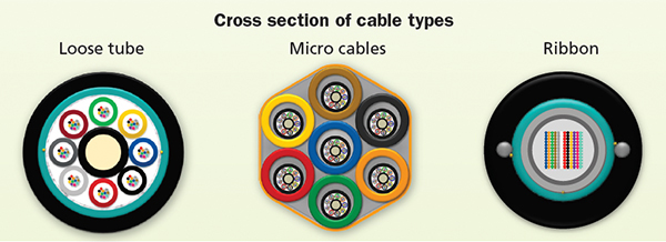
The cable that started the fiber optic revolution in the 1970s was the loose tube configuration, which isolated the optical fiber from the strains of installation by enclosing everything within fairly rigid protective sleeves or tubes. This design is still widely used today in harsh outdoor environments around the globe. 

The 1990s saw the emergence of ribbon cable designs. This cable allowed for higher fiber counts and offered a time and cost savings realized from using mass fusion splicing to speed up network restoration and increase project turnover.

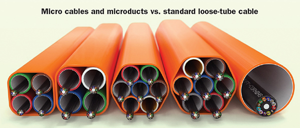
In the early 2000s, micro loose tube cables were first developed in Europe as an innovative approach to installing an optical network in a congested duct environment. These miniaturized stranded loose tube cables, with increased fiber counts per cross-sectional areas, could be installed with less cost and disruption than a rip-and-replace solution. 

Typically, customer segments have standardized on one major cable type for their network or environment. However, as networks grow more complex and bandwidth demands increase, it’s becoming more common for multiple cable families to be used in the same network. In this article, we will look at loose tube, ribbon, and micro loose tube cables and how the properties of low attenuation, scalability, and deployment velocity help define where each cable family fits within different segments of the network.

To being with, you should first understand your specific application and the desired capabilities in order to make smart choices concerning fiber optic cabling combinations. And depending on your specific role, certain cable performance attributes will be more attractive than others. For example, a network owner may be focused on deployment velocity or restoration speed, whereas a network designer may focus on system performance. An installer, on the other hand, may be concerned with safety and cable, and hardware ease-of-use. 


  The major fiber-optic cable families used in outside plant environments are loose tube, micro cables, and ribbon.  


Lowest loss or lowest latency

It’s a safe bet to assume that the end user’s main concern is peak optical performance. Customers demand low signal latency and low attenuation for their optical communication services, and meeting these optical performance requirements is always top priority.

A good option for preventing signal loss is a loose tube design. Since the fiber is under no significant strain, and is generally very tolerant of axial forces, loose buffer-tube cables typically exhibit the lowest optical attenuation losses.

Lower loss performance can also be attained by upgrading to a low-loss fiber which is designed for longer distance applications. Generally speaking, if your system is greater than 100 km in length, low-loss fibers are worth evaluating for overall system cost savings.

Signal latency, defined as the time a signal enters a system until it emerges from that system, can be quantified in milliseconds in the optical communication space. In most typical systems, latency is not an issue and must meet some minimum threshold for satisfactory performance of the network. However, in certain networks, less latency can provide a competitive advantage if you’re trying to deliver your data faster than your competitors. A good example of this is in high-frequency stock trading. Executing trades before the rest of the market, which can often mean beating your competitors in milliseconds, can result in millions of dollars in profit.

Ribbon cable has an advantage in latency because of its inherit design when compared to a loose tube design. In a loose tube cable design, the excess fiber length allows the fiber to reduce or even eliminate the effect of tension on the cable because the fibers float in the buffer tubes. In a typical loose tube design excess fiber length typically runs an additional 2–8 percent of the total cable length. In a typical ribbon cable, there is zero to a fraction of 1 percent excess fiber length.

Let’s look at an example of this by comparing a 550 km segment in a network using either a ribbon cable or a loose tube cable. For a loose tube cable, 5 percent excess fiber would result in a time of flight of 2.826 milliseconds. For a ribbon cable, time of flight would be 2.697 milliseconds. This would provide a latency advantage of 0.129 milliseconds. If you are running a high-speed network, that small amount of time could matter tremendously.


  On the far right is a standard loose-tube cable in a 1.25-inch duct. The other images are various configurations of micro cables and microducts.  


Scalability/future deployments

Growth in fiber-based broadband and the associated network buildouts is exploding worldwide, as service providers race to satisfy demand for bandwidth-intensive services. As carriers begin to support 4G/5G and fiber-to-the-home in access networks, and as cloud service providers link data centers, requests for very high-fiber-density cables — where fibers number in the thousands —are becoming more common.

A general guide on the best cable families to use based on fiber counts needed is if your network is generally below 144 fibers, then loose tube is probably the best option. If your network requires 288 fibers and above, ribbon is probably worth exploring as an option due to time savings in splicing (every network is different, so it’s important to look at other decision parameters in addition to fiber counts). Micro loose tube cables, on the other hand, can act as a bridge option where you can start with lower fiber counts (from 12 to 288 fibers) and then a properly designed system can allow you to scale up in the future with minimal installation cost (more on this below).

There are multiple ways to scale your network for the future either through upgrading to higher transmission speeds or adding more fiber. Generally, leveraging unused fiber is the most cost effective method and is the point of overprovisioning. Depending on a facility’s technology upgrade timeline, it may not be desirable to over-provision fibers from the outset. But one should have the flexibility to group and use the available fibers as needed, and to add additional fibers in the future without a major rework of the whole infrastructure. Typically, Corning recommends overprovisioning in fiber designs in ranges from 25-100 percent based on the uncertainty of future demand. There is no real difference in this approach for a loose tube or ribbon cable — just adding more fibers during initial construction.

With a micro loose tube cable microduct system, there is another approach. An example would be installing a 7-path microduct system instead of a standard cable. In the first microduct you could install a micro loose tube cable from 12-288 fibers. However, you have future potential to install up to six more 288-fiber cables, giving you capacity up to 2016 fibers total. The pay-as-you-go model offered by micro loose tube cables provides an excellent cost-effective option to delay network cost until required, and allows you to leverage new advances in fiber in the future. The figure on the previous page shows various configurations of micro loose tube cables and microducts against a standard loose tube cable in 1 ¼-in duct on the far right.

Installation speed/deployment velocity

Another factor to consider in cable selection is the impact on deployment velocity. Saving time through better cable access and splicing methods can really add up to substantial impact across a network deployment.

Some newer loose tube cable jacket designs, which literally peel off without the use of any tools, can reduce cable access times by 70 percent per cable. If you multiply those savings by the numbers of cables at each access point, you could potentially gain back hours of productivity every day.

Additionally, as fiber counts increase, splicing time per splicing point can become a huge differentiator. One characteristic of a ribbon cable is that fibers are precisely organized for mass splicing or connectorization, making splicing ribbon cables a faster process compared to splicing loose tube cables because you can splice 12 fibers at a time, versus one at a time. This advantage translates into less installation time, less installation labor cost, and significantly less emergency restoration time.

As an example, let’s look at splicing a very high-fiber-count cable. A general rule of thumb is that a single splice takes about four minutes, and a 12-fiber mass fusion splice takes about eight minutes per splice, respectively. Splicing a 1728-fiber count cable (144 mass splices) would take about 19 hours of steady splicing for a ribbon cable. However, splicing a loose tube cable at this level would take approximately 115 hours. If you add those splice counts across a network, it equals a huge increase in time and costs. Although these cable fiber counts seems outrageous for most networks, as we’ve already noted, the demand for fiber counts this size is very real and growing.

Restoration velocity

Regardless of how well an outside plant cable is installed, there is the possibility that something could go wrong. Buried cables can be cut by earth-moving equipment, and aerial cables can be damaged by falling trees. Once unplanned network downtime occurs, your top priority is restoring service to the cable, and doing it as quickly as possible in order to minimize the impact on customers.

We’ve already noted the benefits of ribbon cable in emergency restoration. Using the same criteria above on splicing times, a 144-fiber loose tube cable would take approximately 10 hours to splice and a 144-fiber ribbon cable would take 1.6 hours. One additional consideration in planning for emergency restoration is that when using a loose tube cable the most critical fibers can be identified and spliced by traffic priority more precisely than with a ribbon cable.

A smart network planner makes sure he or she has additional fibers to not only clear a pathway for future scalability, but to also aid in emergency situations. All cables should have spare fibers, especially since fiber is extremely inexpensive compared to installation or restoration costs. Having spare fibers makes it easy to simply switch fibers to restore operation.

Availability limitations

One last area that is worth mentioning is cable availability and the appropriate fibers for different applications. Micro loose tube cables are designed for use in microducts exclusively, so there are no armored cable options. Fiber designs for high-performance applications may not be available in all cable designs because they may not perform well in some configurations. As you explore your options based on the network criteria which is most important for your application, it is wise to have a good understanding of what is available from the different cable manufacturers so that you can eliminate options at the beginning of your search versus after you have made a decision.

The major cable families of loose tube, ribbon, and micro loose tube cables provide options throughout your network that, when used strategically, can offer low attenuation, scalability, and increase deployment velocity. As fiber drives deeper into the network and bandwidth demands continue to increase, examining all your cable options will help you create a network that is future ready and resilient.