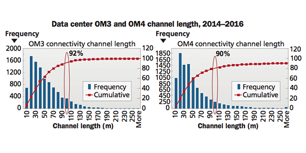
El transporte Fibre Channel es esencialmente conectividad óptica de extremo a extremo. La conectividad de fibra multimodo OM3/OM4 sigue siendo el medio óptico principal utilizado en el centro de datos para distancias de corto alcance de hasta 100-150 m. Actualmente se están implementando 16 redes GFC y 32 GFC que utilizan troncales de fibra óptica multimodo. La fibra multimodo OM3/OM4 permite el uso de láseres emisores de superficie de la cavidad vertical (del inglés VCSEL) para proporcionar conectividad óptica y soluciones electrónicas sinérgicas y de bajo costo.
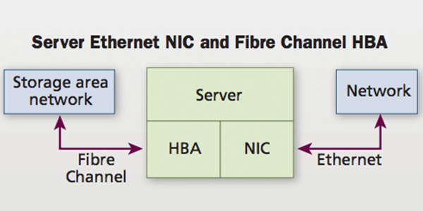
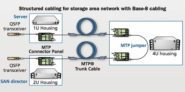
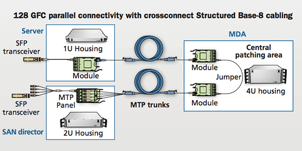
Hasta la fecha, Fibre Channel ha utilizado solo transceptores enchufables de factor de forma pequeño (SFP+), con una interfaz de conector LC dúplex con la electrónica de la red de área de almacenamiento (del inglés SAN) (HBA de servidor, switch direccional y almacenamiento). Los troncales conectorizados MTP® terminados de fábrica se implementan comúnmente desde un área de patch central en el área de distribución principal (MDA) para cada área con servidores, almacenamiento y directores SAN. En el área de patch central, los módulos MTP/LC se utilizan para separar conectores MTP en troncales en puertos LC dúplex. Los puentes dúplex LC se utilizan para proporcionar la conectividad de puerto a puerto necesaria entre dos dispositivos cualesquiera, como el servidor para el director SAN o el almacenamiento para el director SAN.
En gabinetes de servidor y dispositivos de almacenamiento, los módulos MTP/LC se utilizan para separar el conector MTP del tronco en puertos dúplex, para la interconexión con el servidor y los HBA de almacenamiento mediante puentes dúplex LC. En los directores SAN, sin embargo, es común utilizar un arnés MTP/LC en lugar de un módulo para separar el conector MTP del tronco en los puertos LC dúplex. Estos conjuntos de arnés de alta densidad reducen el volumen del cable y la congestión en lo(s) gabinete(s) del director(es), y los terminales LC del arnés se pueden escalar para que coincidan con la separación de puertos de las placas de línea individuales. Este método de precableado del director SAN optimiza la gestión de cables y reduce los riesgos, trasladando el trabajo diario de mover, agregar y cambiar equipos electrónicos al área de conexión pasiva en MDA. Ver figura 5.