By By Ron Gruen and Russell Kirkland, Corning Incorporated
Appearing In Cabling Installation & Maintenance July 2018

Technology inside the data center is changing. But before we spend time discussing how, we need to first start with why. In 2017, nearly a quarter of billion users logged onto the internet for the first time, and the number of users is already up 7 percent year-over-year in 2018. Social media sees 11 new users a second, and the average person is estimated spend at least six hours a day online. Worldwide, there is expected to be an estimated six to seven devices per person globally, and 13 per person inside the US, by 2020. So why is any of that important?
The answer is simple: revenue. Almost all companies have websites that they use to attract and interact with customers, and e-commerce earned nearly $1.5 trillion in 2017. If your website takes more than three seconds to load, you could be losing nearly a quarter of your visitors. Just one second of delay equates to an 11 percent loss of page views and a 7 percent reduction in conversions. A study conducted by Ericsson showed that a few seconds of video buffering can trigger the same increase in anxiety levels as watching a horror movie alone or trying to solve complex math problems. All of this translates to a need for faster connections and greater capacity.
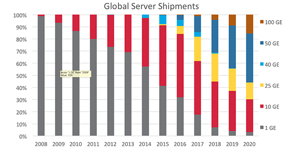
Server activity has increased over the last several years, and this increase is expected to continue. Server speed drives transceiver sales and development. As you can see in Figure 1, 1G connections are quickly becoming relics, and soon 10G will all but disappear as well. 25G transceivers currently have a foothold in the market, but should be eclipsed by 50G over the next few years. Additionally, many hyperscale and cloud data centers are expected to be early adopters of 100G server speeds. These higher server speeds can be supported by either 2-fiber transceivers of equal data rates or parallel optic transceivers of 40, 200, 100, and 400G at the switch utilizing parallel optics and breakout capabilities.
 |
||
Figure 1. Global Server Shipments (source: Dell’Oro Group) |
Transceiver manufacturers use several different technologies to achieve these ever-increasing data rates. Whether the connection between transceivers is made with multimode or single-mode fiber, these different technologies rely on the same basic tools. The first and simplest is just increasing the baud rate. In other words, it’s just how fast you can turn the laser on or off. This first method works well for lower data rates, like 10G, but becomes problematic at higher data rates where the signal-to-noise ratio starts to become an issue.
The next option is increasing the number of fibers. Where you used two fibers to create a 10G or 25G connection, now you can use eight fibers to create a 40G or 100G connection by utilizing several pair in a parallel transmission scenario. Next, we can just increase the number of wavelengths. This is accomplished by using several sources and multiplexing the signal into a single fiber and de-multiplexing the signal once it is received. This is most commonly referred to as WDM, or wave division multiplexing.
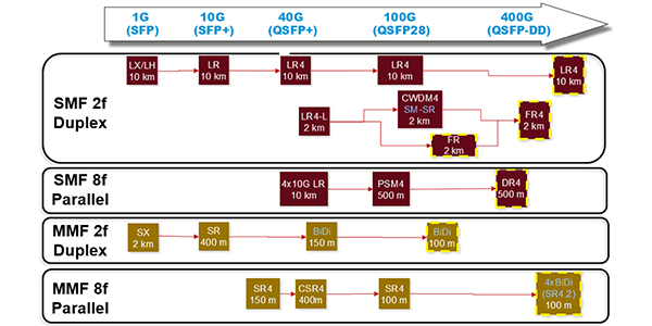
Another method for achieving higher data rates is to change the format of modulation. Instead of using a simple non-return to zero or NRZ, the transceiver can use pulse amplitude modulation (PAM4) to carry four times the amount of data in the same time slot. Higher data rates, whether they use NRZ or PAM4, require some sort of forward error correction algorithm. Because noise has a much larger impact on PAM4, it requires a more complex FEC algorithm. Regardless of which of these methods is used, in the end, you are looking at either a 2- or 8-fiber solution. There are some early 400G solutions that may use 16 or 32 fibers, but either can be achieved using an 8-fiber (base-8) infrastructure.
 |
||
Figure 2. Migration Paths |
Choosing a duplex (2 fiber) vs. a parallel (8 fiber) solution may seem like a simple choice as you look at how transceivers have been traditionally connected, but we’ll take some time to explore both options. We’ll evaluate each option as it pertains to price, power consumption, density, and flexibility.
For enterprise data centers, the average link length is 49 meters, and over 90 percent of the links are shorter than 100 meters. So for most data centers, multimode fiber and associated optics are sufficient for most of the links. For links greater than 100 meters, single-mode parallel optic links are a valid option. Furthermore, the price point for PSM4 and SR4 optics are comparable. For this reason, most hyperscale and cloud data centers employ single-mode links almost exclusively. For duplex connections, new components have to be developed to achieve higher data rates. In contrast, parallel optic connections utilize existing technologies to build next-generation transceivers. Additionally, parallel optics can utilize either four uncooled lasers or a single laser coupled with a waveguide splitter and four modulators. These attributes not only make them cheaper to manufacture but also reduce their overall power consumption.
| Figure 3. Power and Cost Savings with Parallel Tranceivers |
Most data center owners and managers will agree that power is the single largest operating expense inside a data center. For this reason, anywhere that we can lower power consumption will have a major impact on overall opex. A single 10G connection utilizes 1W of power. By contrast, a 40G parallel optic consumes 1.5W of power. Since a parallel optic solution gives you four 10G links per transceiver, you can achieve the same number of 10G connections with a 60 percent power savings. Another consideration to keep in mind is the cost of cooling. As a general rule, for every 1 kW of power your electronics consume, you need 1 kW of cooling. So the reduction in power consumption of the electronics also translates to a reduction in power consumption due to cooling.
Utilizing parallel optic links also helps to drive down the total cost of ownership (TCO) by providing a significantly denser solution. Most high-density SFP+ switch line cards are typically offered in a maximum of 48 ports. You can purchase a high-density QSFP line card with 36 ports. If you operate that line card in breakout mode, each of those ports can now be used as four 10G ports. So with a single QSFP line card, you can support up to 144 10G links. This triples the density of your switch, thereby decreasing the number of line cards you need to support your network. This translates to fewer power supplies, fan trays, supervisors, system controllers, fabric modules, and software licenses. As a result, deploying a system that utilizes parallel optics costs 85 percent less when compared to deploying a system using discrete 10G ports. This reduction in the number of chassis and line cards creates an additional power and cooling cost savings of approximately 67 percent.
In order to utilize any of these cost saving attributes, your structured cabling system must be set up to support an 8-fiber connection. Using a base-8 structured cabling system grants you the most flexibility in system design and clearer migration path to higher data rates. If you employed parallel optics to achieve maximum density and power savings, you now have a clear path to upgrade your system. As the network is migrated from breakout 10/25G to native 40/100G, the existing 40/100G optics and line cards used in breakout mode can continue to be used to operate the native 40/100G links. You now have the capability for two generations of speed out of the switches, line cards, and associated parallel optic transceivers.
As data centers continue to grow there are many concerns facing data center managers. Some of these have been discussed, but this growth also affects the cabling infrastructure that supports these technologies now and in the future. The cabling infrastructure needs to meet the demands of deployment deadlines, needs to be easy to install without the fear of being over engineered, and still have the ability to be easily upgraded to meet the needs of a technology-rich environment. In other words, the cabling infrastructure needs to be reliable (24 x 7 x 365 uptime), flexible (modular to accommodate changes), and scalable (support data center growth).
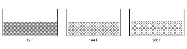
The deployment of structured cabling is not a new concept. Data center environments continue to move away from the practice of patching and connecting equipment as it is installed. Data center optical cabling systems utilize multi-fiber connectors which are referred to as preterminated trunks. Typically, the preterminated trunks are from 12 to 144 fibers and are used to connect different areas of the data center. But the ever-increasing data center footprint and changing network architectures being deployed are causing these typical trunk sizes to be insufficient. These trunks are now required to have fiber counts of 288, 432, and even 576 fibers in an indoor-rated assembly. The use of high-fiber-count trunks will allow for greater fiber density in cable pathways. Larger trunks can also reduce the deployment time required by reducing the number of cable pulls. The reduction of cable pulls also reduces the overall installation cost.
Figure 4 depicts the fiber density for three different deployment scenarios.
4,440 total fibers utilizing 370 x 12-fiber MTP-to-MTP EDGE trunks
13,680 total fibers utilizing 95 x 144-fiber MTP-to-MTP EDGE trunks
16,128 total fibers utilizing 56 x 288-fiber MTP-to-MTP EDGE trunks
 |
||
| Figure 4: Comparison of cable tray fill ratios with different trunk fiber counts (12” x 6”) |
Data centers are starting to grow beyond the confines of a single building or data hall. The largest data centers are growing to include multiple buildings, and these campus environments require the cabling infrastructure to include pre-terminated multi-fiber connector pigtail trunks or bulk cable installations. These pigtail trunks utilizing indoor/outdoor cable can have fiber counts up to 864 fibers. The connectivity requirements are pushing the bulk cable fiber counts beyond 864 fibers, up to 1,728 and 3,456 fibers.
Structured Cabling Solutions
Various solutions can be deployed to meet the high-fiber-count requirements. We will discuss three options that can be utilized depending on the installation environment. The one constant in all these scenarios will be the use of multi-fiber connectors. These connectors result in faster installation times and provide a path from 2-fiber transceivers to 8-fiber transceivers. Utilizing structured cabling and multi-fiber connectors will allow for the deployment of breakout applications which can reduce the TCO.
Multi-fiber Connector Trunks
Multi-fiber trunks are deployed when connecting areas within a data center to each other. For example, the main distribution area (MDA) to the horizontal distribution area (HDA) or to the equipment distribution area (EDA). The trunks will land at a fiber distribution housing with the multi-fiber connectors of the trunk to a module or adapter panel with the housing. This allows for connections to the active component via a jumper. MTP trunks are deployed within one room of the data center, but can be pulled to adjacent rooms if pathways will allow for the passing of a pulling grip which houses the multi-fiber connector and protects them. One important thing to be mindful of is that the deployment of these trunks takes careful planning to ensure proper trunk lengths are correct and clear pathways are attainable.
2. Multi-fiber Connector Pigtail Trunks
Pigtail trunks are deployed in one of two applications.
- When there is a congested pathway (duct) and pulling grips cannot be pulled through those pathways.
- When connecting data center rooms from different floors of a building or different buildings on a data center campus.
In addition to the previous applications, a pigtail trunk may be desirable if the exact distances between two areas of the data center are not exactly known.
After the pigtail trunks are pulled, additional steps are required to prepare them for termination. These steps include accessing the cable to expose the fiber and furcating the cabling to protect the fibers in the rear of the fiber distribution housings. The bare end of the cable will terminated with multi-fiber splice-on connectors, pigtailed assemblies, pigtailed cassettes, or a pre-stubbed housing.
3. High-fiber-count cables
High-fiber-count cables utilize ribbonized fiber to maximize the fiber density in one cable. The ribbon cables have a small outer diameter (OD) compared to the fiber density, which allows the cables to be deployed in congested pathways. As mentioned earlier, these cables can contain 864, 1728, and 3456 fibers.
Termination of these cables can be performed using multi-fiber connectors, pigtailed assemblies, pigtailed cassettes, or a pre-stubbed housing. These types of deployments can result in increased deployment times compared to preterminated cables. This is because the both ends of the cable need to be prepared for termination with furcation kits that protect the ribbon fiber in the fiber distribution housing. The optical performance of the field-terminated cables may be not be as good as factory preterminated cables.
 |
||
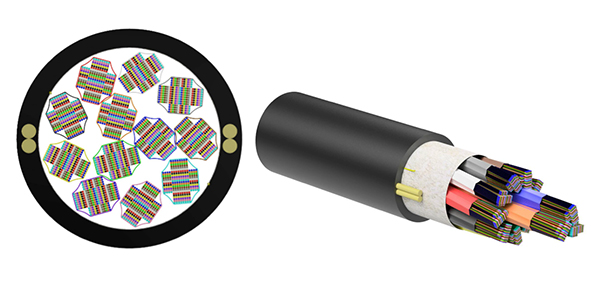
| Figure 6: 3,456-Fiber Extreme-Density Cable |
Summary
We have discussed many of the topics that data center managers must consider when planning for a new data center. As the size of data centers continues to grow, these topics only make the planning more challenging. But being aware of the increasing technology changes and future data center requirements can make the data center design process more rewarding, and could also increase TCO.