by Anthony Robinson, RCDD CDCDP® CNIDP® Corning Incorporated. Originally published ICT Today

Blockchain and the Cloud: Transforming Data Center Architecture for Tomorrow
Blockchain and the Cloud: Transforming Data Center Architecture for Tomorrow
Data Center Trends: Blockchain and Clouds
Enterprise data centers have traditionally focused on data storage and preparation for disaster recovery, but they don’t always meet the ebb and flow of demand for real-time, multi-user data retrieval. In today’s evolving digital market, there are more users and more data. This growth puts pressure on data centers to facilitate faster data transmissions for an increasing number of internet users worldwide. In the face of big data, data center operations are shifting from storage to the real-time analysis and processing of data based on demand.
Today, organizations are turning to the blockchain for their data centers, a system that acts as a digital record-keeper, utilizing multiple hardened data centers around the world to verify changes to data sets. Blockchain will reinforce the need for secured infrastructures based on networks of data centers. According to the Research and Markets research firm, the market for blockchain is set to jump from $1.2 billion in 2018 to $23 billion by 2023, in part due to the development of enterprise-facing applications and services outside of traditional finance and transaction functions. Data centers must adapt to new business strategies.
In order to pave the way for technologies like this, large data centers are evolving their digital infrastructures, driven by the rapid growth of cloud computing. Many companies, including internet giants, are increasing investments in data centers both domestically and abroad, to ensure they are ready for the next generation of cloud services. But they need the right data center infrastructure in place to ensure the rapid and seamless transmission of data, voice, and video to an increasing number of users. And not only that, they need a secure way of keeping track of sensitive data. For these reasons, many data centers are transitioning from current 3-level tree network architectures to a spine-and-leaf network architecture, which can accommodate blockchain systems and increasing data processing demands. But what does this shift entail?
3-Level Network Structure vs. 2-Level Spine-and-Leaf Network Structure
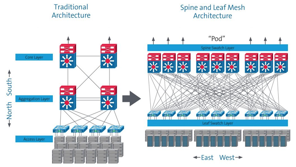
In contrast to the traditional enterprise, where data center traffic is dominated by local client-to-server interactions (north to south), the network traffic of the large internet data center is dominated by the server-to-server traffic (east to west) required for cloud computing applications. The number of users accessing data via applications is not only huge; they also have diversified and fragmented demands and require an uninterrupted user experience. Internet data centers require higher bandwidth and a much more efficient network architecture to support spikes in heavy traffic from their large number of users. These spikes in data traffic could be driven by anything from video calling, demand for online music and videos, gaming, shopping, news events, and more.
The current mainstream 3-level tree network architecture is based on the traditional north-to-south transmission model. When a server needs to communicate with another server from a different network segment, its server must pass through the path of access layer -> aggregation layer -> core layer <- aggregation layer <- access layer. In a big data service with thousands of servers communicating in a cloud computing environment, this model is not effective as it consumes a large amount of system bandwidth and creates latency concerns.
To address these challenges, the world's large internet data centers are increasingly adopting a spine-and-leaf network architecture, which is more effective for transferring data between servers (east to west). See Figure 1.
 |
||
Figure 1: Traditional 3-Level vs. Spine-and-Leaf 2-Level Network Architecture |
This data center network architecture consists primarily of two parts – a spine switching layer and leaf switching layer. Its most beneficial feature is that each leaf switch is connected to each spine switch within a pod, which greatly improves communication efficiency and reduces the delay between servers. In addition, a spine-and-leaf 2-level network architecture avoids needing expensive core-layer switching devices and makes it easier to gradually add switches and network devices for expansion based on business needs, saving on the initial investment costs.
Dealing with the Cabling Challenges of a Spine-and-Leaf 2-Level Architecture
Data center managers encounter new issues when deploying a data center with a spine-and-leaf 2-level architecture. Since a leaf switch is required to connect each spine switch, managing a massive quantity of cabling becomes a major challenge. Corning’s mesh interconnection module (Table 1) solves this difficult problem.
Table 1: Mesh Module
| 4x4 Mesh Module | Description |
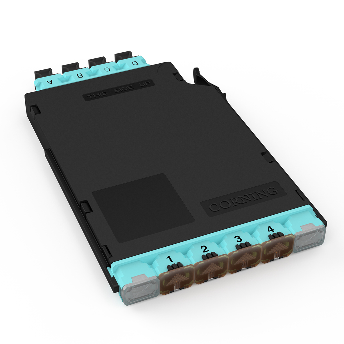 |
4 x 8 fiber MTP® input port,4 x 8 fiber MTP output port Fiber type: OS2 and OM4 SR4 vs. PSM4 meshed interconnection does not need LC port conversion |
Many users have started using high-density 40G switch line cards to break out as part of 10G applications. In fact, according to the transceiver vendors, more than 50 percent of all 40G multimode deployments are taking advantage of this capability. For example, a high-density 10G SFP+ line card has 48 x 10G ports, while a high-density 40G QSFP+ board may have 36 x 40G ports. As such, a 40G line card can be used to obtain 4x36 = 144 x 10G ports in the same cabling space and power consumption conditions, thus lowering the cost and power consumption of the single-port 10G. These cost savings can also be appreciated as the speeds increase further to 100G, and we saw announcements at the end of 2018 that 400G will start shipping this year, both with the ability to break into lower speed server connections.
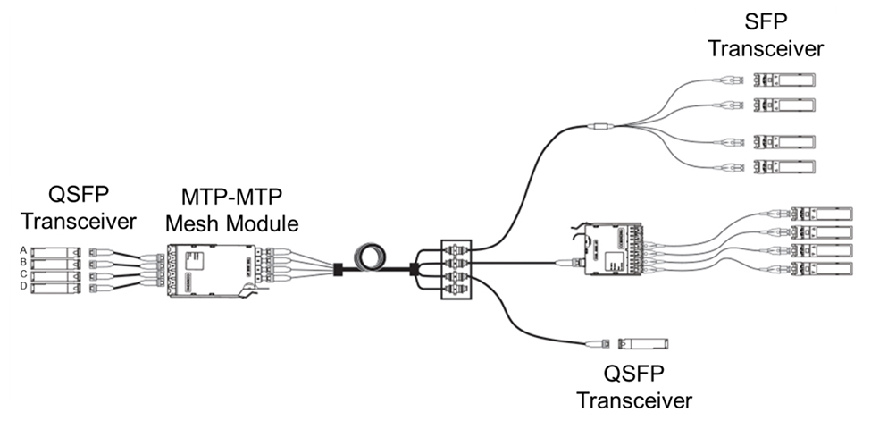
For simplicity purposes we will stay with the 40G breakout example. Figure 2 shows three typical applications of mesh modules in the cabling system. Four QSFP 40G channels (A, B, C, D) are broken out into 4x4 10G channels at the MTP input of the mesh module. The 10G channels are then shuffled inside the mesh module so that the four 10G channels associated with QSFP transceiver A are split across the four MTP outputs. The result is that the four SFP transceivers connected to the one MTP output receive a 10G channel from each of QSFP transceivers A, B, C, and D. Thus, we achieve a fully meshed, 10G fabric connection between the QSFP spine switch ports and the leaf switch ports without ever having to break out to LC connections at the main distribution area (MDA).
 |
||
| Figure 2: Three typical applications of mesh modules in the cabling system |
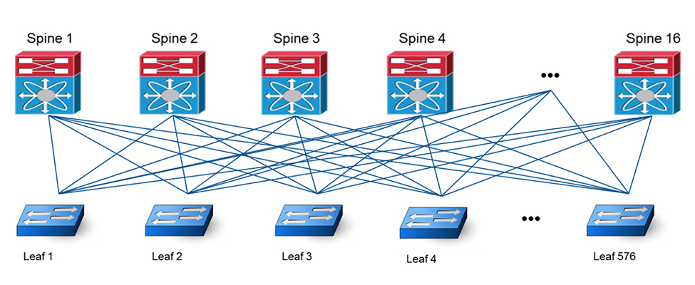
The example below depicts how to optimize the cabling structure of a spine-and-leaf at the MDA. For example, we use a leaf switch with a 48 x 10G SFP+ port line card and a spine switch with 4x36 40G QSFP+ port line cards. If a leaf switch has an oversubscription ratio of 3:1, 16 x 10G uplink ports of each leaf switch need to connect to 16 spine switches. Given that the 40G port of the spine switch is used as four 10G ports, each spine switch needs to connect 4x36x4 = 576 leaf switches as shown in Figure 3.
 |
||
| Figure 3: Spine-and-leaf 2-level network topology in a 10G application |
 |
||
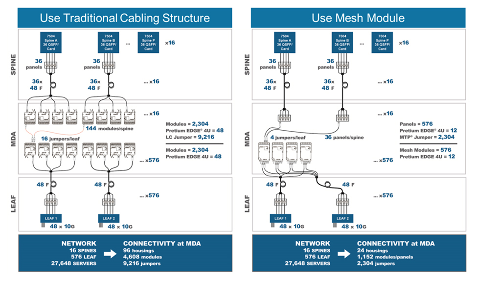
| Figure 4: Full cross-connection cabling structure comparison of spine-and-leaf network architecture MDA |
If traditional cabling is used to achieve full fabric mesh of the spine and leaf switches, a 40G QSFP+ port of each spine switch is broken out into 4 x 10G channels through an MTP-to-LC module in the MDA and then cross-connected through a patch cable with the corresponding number of the MTP-to-LC modules that connect to the 10G channels of the leaf switch (as shown on the left side of Figure 4). The traditional method has not been widely used because the cabling system is very complex, the cost is relatively high, and it requires a lot of rack space at the MDA. In this scenario, the use of a mesh module can be a good solution to resolve these problems. As shown in the graphic on the right side of Figure 4, in the case of a network module used in MDA, the full mesh of the leaf switches is achieved without having to break out the 40G port of the spine switch into 10G channels via an MTP-to-LC module. This greatly improves the MDA cabling structure by eliminating massive LC-to-LC patch fields and can be of great value for the user, as shown in Table 2.
Table 2: Advantages of a Mesh Module in the MDA
| Advantages | Value |
| Density | Save MDA distribution space by 75% |
| MTP connections | Reduce number of jumpers in MDA by 75% |
| Link-loss | Decrease link-loss by 10% |
| Cost | Reduce installation cost by 45% |
Blockchain in Data Centers
Once the proper infrastructure is in place to support the growing amount of data traffic, data centers can better secure that data. Blockchains have become popular solutions through recent examples like Bitcoin and Ethereum, but they are not limited to the financial sector. The technology is a sort of external ledger. Its cryptographic method can distribute data across multiple computers, which makes it more difficult to hack.
One major characteristic of blockchain is its tendency toward a “shared community,” where private users can rent out extra space on their hard drives for other users to store data. This, however, does not eliminate the potential for commercial interest. Data centers that implement the blockchain technology can provide clients with an even more secure storage method for sensitive information.
Conclusion
Data center network infrastructures are going through major transformations to meet the demand of continuously growing data traffic and the need to securely store sensitive information. At the same time, they must support the Internet of Things, 5G networks, and billions of new devices, while continuing to supply the increasing speed and scale required for this interconnection.
Data centers are changing, not just on an architectural level, but on a physical one as well. There are more and more multi-fiber connections providing high-density connections. The 10G interface is no longer sufficient to support the bandwidth demands of the data center.
As network bandwidth requirements for the data center rise, the backbone of the data center network has been gradually upgraded from 10G to 40G, with 100G deployments becoming the norm. By using 40G broken down into 4 x 10G now, or 100G as 4 x 25G the spine-and-leaf network architecture will deliver an economical and efficient network structure for the management of large data distribution. Utilizing the mesh module to achieve a full fabric mesh of the spine-and-leaf network supports the current 40G or 100G network while ensuring the seamless transition to future 400G network capabilities as user demand grows.
Not only must data centers evolve to meet the demand of higher traffic and more devices, but they must also prioritize securely storing users’ sensitive data. By transforming their data center network architecture and adopting a blockchain strategy, they can take the next step forward to a completely connected society.
Contact Us
For prompt assistance, please complete the form below and one of our representatives will contact you.